|
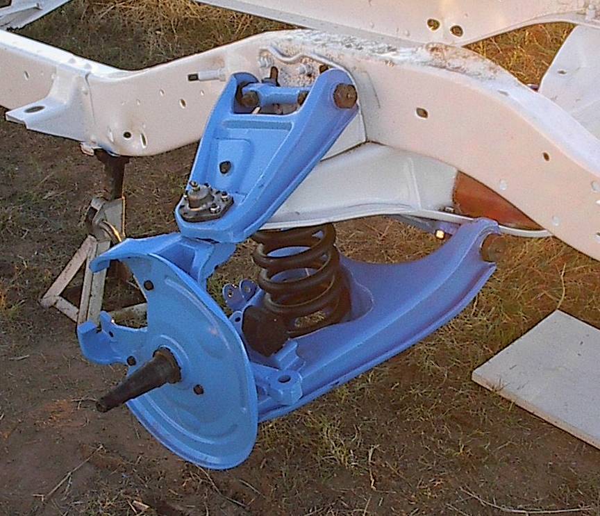
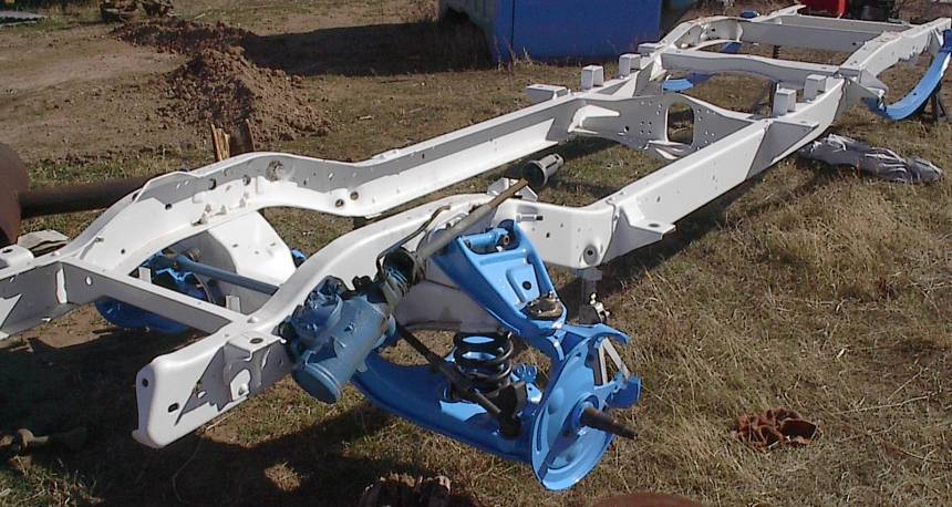
Adding power brakes to these particular trucks is very simple. To start find a donor vehicle in good shape and you can
proceed one of two ways to do the swap. The first you can remove the entire front crossmember unit and bolt it to the underside
of the older 63-66 gmc frames. The other way if you prefer the original suspension arms and brackets involves getting the
spindles from the newer truck and having newer ball joints from the donor truck year installed into the a frame arms. Once
that is done you can bolt up the newer brakes easily. The newer ball joints are a shade longer than the originals so you at
least need a set of those. The upper ball joints are identical in length and bolt pattern. Take a look at the picture
below and it will show the 2nd way of performing the swap.
Power Steering Conversions
To do the power steering conversion for the truck I went with a REZ Engineering power steering conversion kit. They claimed
it was an easily performed modification that did not require welding to the frame. I have to say the kit was excellent after
about three hours I had a new power steering box installed on the truck. *Make sure to use the original center steering
bar.* If you use the newer center steering link it will not have enough clearance from the
front engine mount crossmember. When it is all completed it came out that the idler arm was at most a 1/4" off
the original factory specs which is quite a feat that it came out so close to the original specs, considering you have 1/8
inch spacers between the new plate and the steering box. I am switching my 3/4 ton truck to a shortbed frame and will take
some detailed photos of the power steering bracket adapters and install photos.
I later have plans to purchase a Ididit
steering column and borgensen shaft assembly to connect the box and steering column.
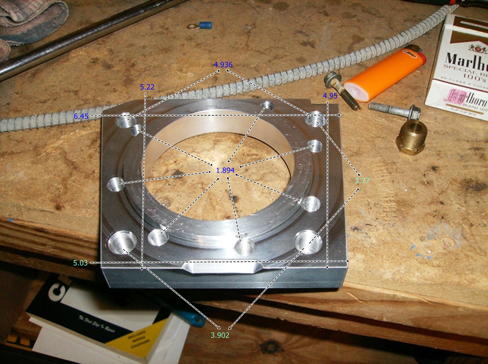
Above is the disc brake adapter plate. the numbers you see when you open the picture are in inches. the number in the
direct center of the bracket is the bolts to backing plate center to center bolt measurements. the outer holes you get the
idea. each of those are center to center of each bolt measurements.
|
 |
|
|
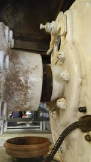
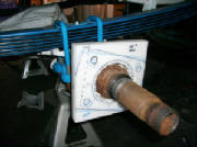
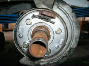
Below you can see the old backing plate before removal. It was a sun of a gun to get off and had to use the grider to
get most the nuts loose. Make sure dammed sure the company you have to do your powder coating does the job right the first
time.
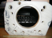
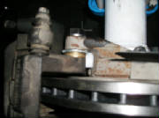
Below you can see themock up delrin we are using to get everything set into place atm. The machinist is going to cut
off the areas outside the black lines so the new backing plate will mount to this piece and allow all the brakes to mesh with
the rotor. Will have approximates thickenesses here in another week to two weeks.
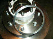
Above are some pictures of the centering ring that is keeping the rotor centered on the older hub so far things are looking
great att his time. Will know more when I can get everything bolted onto the axle and start working on the block thickness
for properly braking.
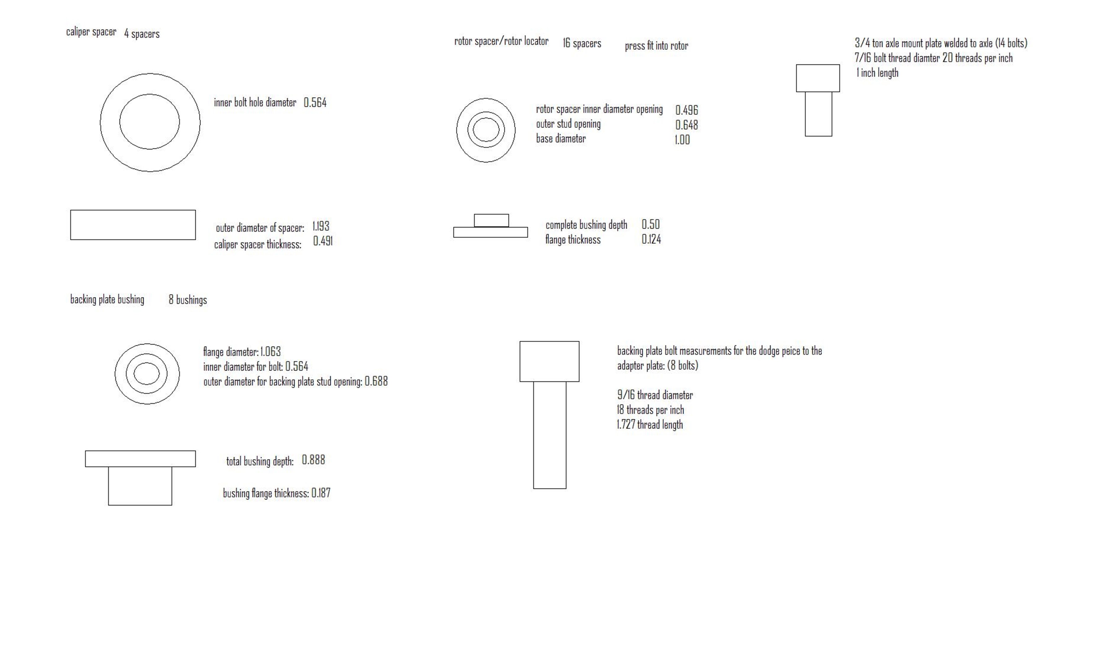
Above you can see the parts needed to adapt the dodge disc brake sonto my older axle. To download this open the picture
in a new window and right click on the picture to save it too your computer. It can be veiwed in paint any jpeg viewer and
microsoft office. Large enough so that it is legible to be read.
|
|
|
|
|
below is a preliminary picture of the adapter block that were are using delrin till we have the final measurements ready
to machine the aluminum for this project.
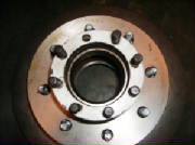
Below is the backing plate from the dodge 1 ton mounted in place with the backing block on the axle and secured with
4 bolts for now.
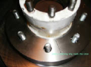
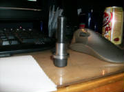
Below is a picture of the stainless steel locator bushing design to keep the backing plate from moving around. The plastic
adapter block has a machined ring on it as well to keep this bugger centered and in proper alignment with the rotor.
Below is a picture of the spacing I had to do to the caliper bracket to get it centered on the rotor there is about .90
inches between the pads and rotor on both sides at the moment. That will of course be sucked in when the brakes are activated
for the first time.
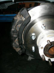
Above is the setup completely bolted into place I found I had to space the rotor out some to get it away from rubbing
on the backing plate. So it will go back since I have the depth the block needs to be thinned to accomodate the rotor now
:D. Coming along awesome will be back with the machinist on wednesday for more work and start getting him paid. He does some
fantastic work. I reccommend getting to be friendly with retired aerospace machinists and engineers!
|
|
|
|
|


